Would it be better with this element?
Not really. A zener diode needs several mA of current for regulation. In this regard it is no better than the 7812 regulator mentioned above.
Before you start looking for solutions we need to know if the output shall be a constant 12 V or a factor of the battery voltage.
I do not know the interfaces to the power tools mentioned - no Dewalt tools here - so I cannot answer that question.
Karl seems to favor a factor of 3/5 and for that a voltage divider with two resistors (10k + 6.8k) will do the trick and is easy for you to accomplish.
Is it the ideal solution? No, of course not. It slowly drains the battery over time. So you need to disconnect the battery after use.
There are ways to prevent this.
For a factor of 3/5 as the output voltage:
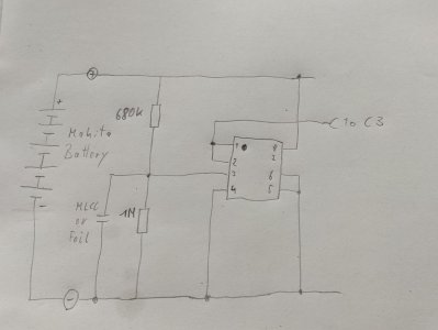
I would use a high impedance voltage divider (1 meg to 680k) with a 1 nF MLCC in parallel to the 1 meg resistor and then use an opamp as a non-inverting amplifier with a gain of 1. If a low-Iq opamp like the Analog Devices LT2178 is used total no load current of the circuit is less than 0.05 mA and the output is stable even under load (up to 5 mA).
Same for the 12 V fixed output if that is really required:
I would use a low quiescent current linear voltage regulator like the TI TPS7A24, which without a load current can easily get into the single digit µA Range - that's better than the 7812 or zener variants by a factor of 1000.
However, both solutions are most likely not useful for you because they require soldering extremely small ICs plus several external components.
So let's first answer the question of the output voltage of this circuit and then we can find a useful solution - which depends on at least three factors: Maximum acceptable load on the battery, the space available inside the housing and your soldering skills.

Noch mal die
Kurzzusammenfassung auf Deutsch:
Zenerdioden brauchen mehrere mA Strom, um richtig zu regeln.
Erst klären, ob der Ausgang feste 12 V haben soll oder einen Faktor von z.B. 3/5 der Akkuspannung. Bei letzterem: Spannungsteiler aus 10k + 6k8.
Bessere Lösung für 3/5*U_bat: hochohmiger Spannungsteiler 1meg+680k mit Abblockkondensator und OPV als Spannungsfolger, z.B. den LT2178 um auf < 0.05 mA Verbrauch zu kommen.
Bessere Lösung für 12 V fix: LDO mit niedrigem Querstrom, z.B. TPS7A24, so dass man auf < 0.01 mA kommt.
Beides sind kleine, für Anfänger schlecht zu lötende ICs, die auch noch weitere externe Komponenten brauchen. Daher ist das in diesem Fall wohl zu schwer.
Also erst klären, ob 12 V fix oder 3/5U_bat und dann eine passende Lösung auswählen. Stromverbrauch, Baugröße und Lötkenntnisse sind die relevanten Kriterien.


 to the people who helped me with the necessary information. Thanks again